The recent cull in electrification projects in the UK has seen a rise in the exploration of alternatives, particularly alternative fuels. Although this is an attractive option, types of discontinuous electrification may be a better, and longer term, solution. IPEX has recently run several projects working to develop strategies for long term alternatives. In the next two IPEX Industry Insights, we aim to discuss two types of discontinuous electrification, examining the cases for: majority electrification with gaps only employed where infrastructure issues are costly or insurmountable; and electrification hubs with considerable distances without electrification using battery power to bridge the gaps.
Reducing railway electrification costs
Electric trains have several significant advantages over diesel trains.
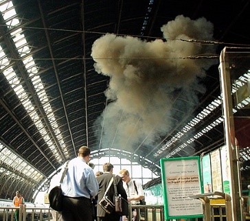
Fig. 1: Diesel fumes in St Pancras station (before modernisation) © urban75In particular, the size, weight, complexity and maintenance costs of an electric train’s on-board power equipment is typically much less than that of a diesel train with comparable performance. Their impact on the environment and the travelling public is also kinder.
The National Grid enables appropriate technologies and processes to be used to minimise the cost of electricity in both economic and environmental terms, and railway electrification passes these benefits on to the trains that use it. However, the investment needed to install the necessary railway electrification infrastructure is huge, and this reality continues to prevent the majority of the UK network from being electrified.
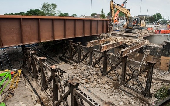
Much-needed electrification schemes can be rendered unviable because of the disproportionate cost of infrastructure clearance work. For example, if a bridge is below a certain height and the track cannot be lowered, it may need to be demolished and completely rebuilt.
Fig. 2: Ardleigh Green Bridge replacement © TfLOne way to reduce infrastructure clearance costs is to leave gaps in the overhead line equipment (OLE) where non-compliant structures exist, and use on-board energy storage systems to power trains across these gaps. This concept is known as ‘discontinuous electrification’.
Examples of discontinuous electrification schemes
The diagrams below provide three examples of discontinuous electrification schemes. The scenario is a branch line off an electrified part of the main rail network, such as the Windermere branch. In this hypothetical example, there are two low bridges over the line, which would require difficult and expensive work to enable electrification. The ‘£’ symbols represent the money spent installing the electrification.
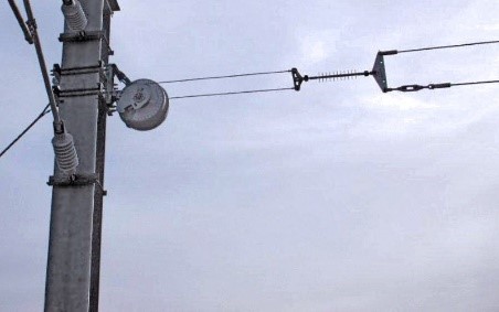
Fig. 3: Catenary termination: Tensorex C+ tensioning device © Intertech EngineeringIn the first solution, the electricity is carried all the way to the end of the route, but the OLE is absent through and between the bridges and replaced by a buried cable. This approach is only viable if the trains have sufficient battery autonomy to run the length of the gap.
It would be possible to install OLE between the bridges but, in this example, it is assumed that the distance between them is too short for this to be appropriate.
Fig. 4: First solution – electrification to end of route; buried cable through and between bridgesThe second scheme shows an alternative approach. In this, the high cost of rebuilding one bridge is justified because it enables the OLE to be run all the way to the second bridge, at which point it ends completely, thus saving the cost of any further OLE and buried cable. This approach is only viable if the trains have sufficient battery autonomy to run twice the length of the gap (there and back) and run their auxiliary loads for the whole time, including the station dwell time.
Fig. 5: Second solution – first bridge rebuilt; termination before secondThe third scheme shows another alternative. In this, the rebuilding of the first bridge has been avoided by running a neutral section through it. As explained later in this article, this option is typically only feasible for a small proportion of structures.
Fig. 6: Third solution – neutral section through first bridge; termination before secondPrior research
In 2009-2010 RSSB (the UK Rail Safety and Standards Board) commissioned a suite of research projects.
- Project T777 concluded that OLE featuring gaps is a feasible proposition that could significantly reduce the cost of electrification.
- Project T778 found no fundamental reason why pantographs cannot be routinely raised at speeds up to 100 mph or more.
- Project T779 concluded that one of the problems with OLE featuring gaps was that the entire fleet of trains would need to be fitted with storage devices, introducing severe constraint on operation. However, it suggested that future technologies may hold a key to make this application possible.
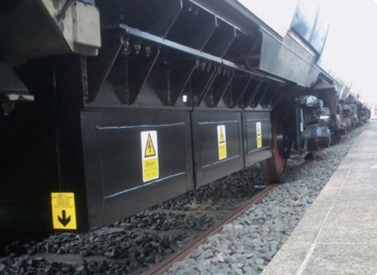
- In 2015, an Independently Powered Electric Multiple Unit (IPEMU) trial train was created from a standard 4-car Class 379 ‘Electrostar’ 25kV EMU on which two rafts of batteries were installed temporarily. These two rafts had a combined weight of ca. 8 tonnes and a total energy storage capacity of ca. 450kWh. The unit’s power rating while running on these batteries was ca. 950kW (which is just over half of its rating on 25kV). The train ran between Harwich and Manningtree, on battery power in one direction and 25kV in the other (recharging the batteries while running on 25kV). The distance between the stations is 11.1 miles and a top speed of 60 mph was achieved on battery power. The train is reported to have performed in all aspects like a standard unit and consistently achieved the acceleration rates required by the timetable.
On-board energy storage solutions
Batteries
A suitably sized battery is able to store sufficient energy and produce sufficient power to propel a road or rail vehicle at reasonable speeds over reasonable distances. It can also absorb power (during charging) at a similar rate.
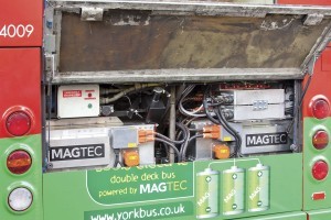
Fig. 8: The MagTec electric sightseeing bus in York © Bus & Coach BuyerA good example of this application is the electric sightseeing bus produced by the innovative propulsion system developer Magtec, which is now operating in the city of York, running all day long without charging, with a range of over 70 miles. The new electric drive train with two battery packs easily fits within the space vacated by the diesel engine, transmission and cooling system.
Fig. 9: The battery packs in the Magtec bus © Bus & Coach BuyerAlternatives
Capacitors are able to charge and discharge at high power levels due to low internal resistance giving them the capability to absorb and redeliver energy very quickly. They are therefore well suited to capturing energy generated during braking, as well as short-term boosting of traction power. Their inherent disadvantage is that they can only store a fraction of the energy that can be stored by a battery of a similar size and weight.
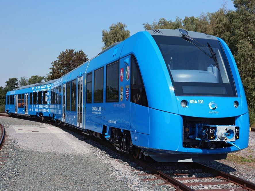
Hydrogen fuel cells could provide a good future solution for diesel replacement on long, lightly used routes. Other emerging energy technologies also present promising prospects. However, on heavily used routes (such as Trans-Pennine) and short non-electrified branches connected to electrified routes (such as the Windermere branch), electrification provides a robust solution that is already available. Such schemes are viable today and will remain viable in the future.
Fig. 10: Alstom’s ‘iLint’ hydrogen-powered unit © Railway Gazette InternationalElectrified railways will always benefit from improvements in energy generation and storage technologies as they continuously improve the affordability and sustainability of the electricity supplied by the National Grid.
Can it really work?
Power and energy principles
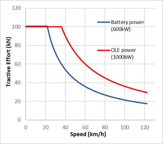
A typical 3-car electric train might weigh in the region of 100 tonnes and accelerate from rest at ca. 1m/s2. To achieve this acceleration, it would require 100kN of tractive effort (TE).
At low speed, power consumption is low because energy is a function of force multiplied by distance, which is only covered slowly at low speed. As speed increases, the rate of delivery of energy (power) to the wheels increases. Once the power limit is reached, the rate of delivery of energy to the wheels cannot increase any further, so the TE has to fall as the speed continues to increase.
The graph above illustrates this principle. Two lines are plotted as examples for a hypothetical train that can drive on either battery power or power from the overhead electrified line (OLE). The example train has a lower power rating in battery mode (600kW) than in OLE mode (1000kW).
With 600kW available, the train can accelerate as fast in battery mode as it can in OLE mode up to 6m/s (22km/h). Above that speed, the TE falls in inverse proportion to speed. In OLE mode, the TE only starts to reduce after 10m/s (36km/h).
The energy used per km for acceleration is TE x distance. Therefore, while the TE is at its highest (100kN), the energy usage per kilometre is 100MJ (100kN x 1,000m) or 28kWh. Once the TE starts to reduce, so the energy per km also falls as a result.
Realistic assumption for typical operation
Peak power would only be used for a small proportion of a typical journey. Information obtained from various train manufacturers indicates that a unit weighing in the region of 100 tonnes would typically be expected to use between 6kWh and 10kWh per km in normal service.
Battery capability
Prudent estimate of energy available
Battery manufacturers typically consider a battery to have reached the end of its useful life once its capacity has deteriorated to 80% of its as-new capacity. They recommend that a battery should not be discharged below ca. 10% and caution that the rate at which a battery can accept charge tends to become very low as the charge level approaches 100%. This means that the amount of energy available from a fully charged battery on a train might only be 64% (80% x 80%) of its quoted as-new capacity. On this basis, to ensure that 100kWh of energy would actually be available, the battery specification would need to be 156kWh.
Fig. 12: Some of the battery packs on the ‘IPEMU’ trial train © BombardierBattery technology is becoming increasingly able to provide well over 100kWh on a 100t train: for example, the electric sightseeing bus mentioned above has a 133kWh battery.
Optimising battery life by managing duty cycle
Another recommendation from battery manufacturers is that the useful life of a battery is significantly reduced if its duty cycle involves repeatedly varying its level of charge by more than ca. 35% of its nominal capacity (for example, from 90% to 55%).
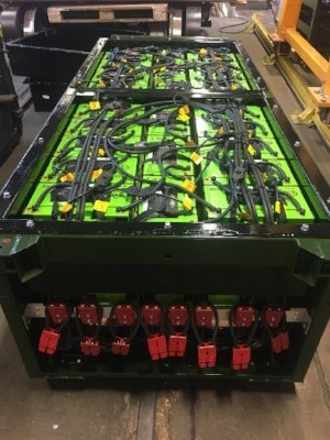
Fig. 13: Battery module for Vivarail’s Class 230 battery unit © Vivarail Ltd
A battery can be recharged at a similar rate (power) to the rate at which it can discharge power. This means that, if a train runs in a non-electrified gap for a period of time, the energy discharged from the battery during that period can be replaced in a similar time period once it returns to the OLE.
For optimization of whole-life cost and performance, the above principles would need to be reflected in the design of a discontinuous electrification system.
Operational Resilience
Trains must be able to operate near-normally in disruption/emergency scenarios, and battery-powered trains are no exception. This means that the battery must have sufficient capacity to get out of any foreseeable adverse scenario, such as the following.
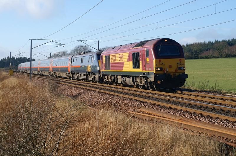
Fig. 14: A diesel locomotive hauling an electric train © Steven J CrozierConsider a 100t unit trying to propel a failed unit up a 1 in 40 gradient. Each unit might be laden with 300 people adding 24t per unit. The total weight of the consist would be just under 250t. With 100kN of TE, the acceleration would be 0.4m/s2 on level track. On a 1 in 40 gradient, the loss of acceleration due to gravity would be one fortieth of the gravitational constant (9.8m/s2), which equates to 0.25m/s2. On a 1 in 40 gradient, the train would therefore accelerate at only 0.15m/s2.
If (for example) the battery power rating were 600kW, the tractive effort of 100kN would be available up to 6m/s, after which it would decline in inverse proportion to speed. At an acceleration rate of 0.15m/s2, 6m/s would be achieved after 40s, during which time the consist would cover 120m.As explained above, with maximum TE being applied, the energy consumption would be 28kWh per km up to 6m/s, after which it would start to decline in proportion to the declining TE. At 12m/s (43km/h) the TE would be half of 100kN and the rate of energy consumption would therefore be only half of 28kWh/km.
As explained above, with maximum TE being applied, the energy consumption would be 28kWh per km up to 6m/s, after which it would start to decline in proportion to the declining TE. At 12m/s (43km/h) the TE would be half of 100kN and the rate of energy consumption would therefore be only half of 28kWh/km.
This analysis indicates that, although the energy usage per km would be 28KWh/km initially, it would start to reduce after only 120m, and could be expected to settle at a rate of no more than ca. 15kWh/km.
Fig. 15: Passengers being evacuated from an SMRT train in Singapore © The Online CitizenAs explained above, if the battery capacity were 100kWh, a prudent estimate of the energy available would be 64kWh. In this case, the battery would be able to power the consist for at least 3km.
Optimising the system
Rolling stock
Energy storage capability significantly increases the cost of a train and can be difficult to achieve due to space and weight constraints. Therefore, if the number and lengths of gaps in the electrification system is as low as practicable, this helps to reduce the capital and maintenance costs of the trains.
Fig. 16: Hitachi’s ‘DENCHA’ train © HitachiHitachi’s ‘DENCHA’ (Dual ENergy CHArge) train runs on the Japanese island of Kyushu. The 2-car unit carries a total battery capacity of 384kWh, made up of three battery packs, each of 128kWh capacity and weighing in the region of 1 tonne and each occupying about 4m of underframe space. Japanese Railways (JR) sees electric trains with battery energy storage capability as a cost-effective alternative to purchasing new diesel trains.
Infrastructure
It is reasonable to assume that the cost per mile of a gap is much less than half of the cost of electrified plain line. However, this is not a good reason to incorporate long gaps in a discontinuous electrification system. The most efficient way to achieve good train performance (acceleration and recovery of braking energy) is to provide as much OLE as is feasible.
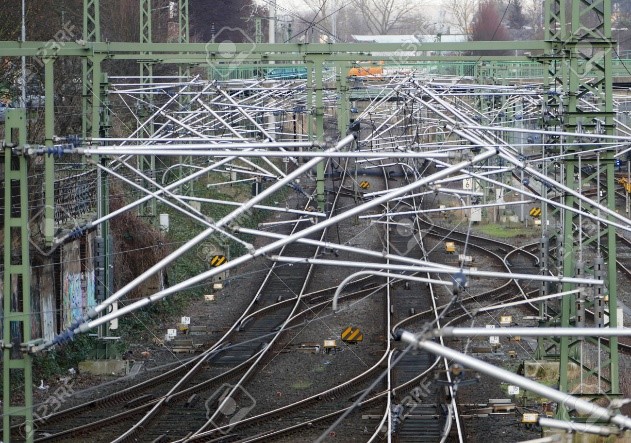
Fig. 17: Complex infrastructure © The MasterbuilderAs a general rule, gaps should therefore only be used to avoid structure clearance work, but where multiple gaps are necessary, consideration should be given to merging two or more small gaps into fewer, longer gaps, for two reasons:
- Additional costs are incurred in terminating the OLE before and after gaps.
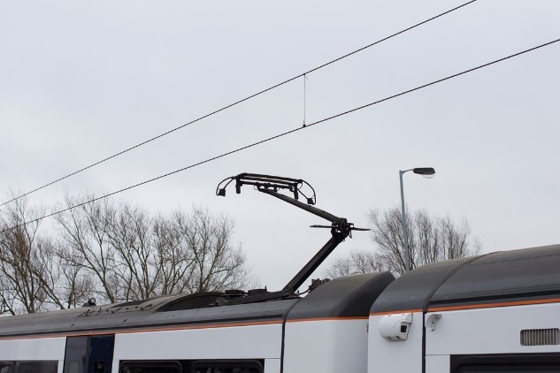
- A train requires several seconds to go through the process of separating itself from the conductor and then reconnecting, noting that a pantograph cannot be hurried because of the need to finely control contact force.
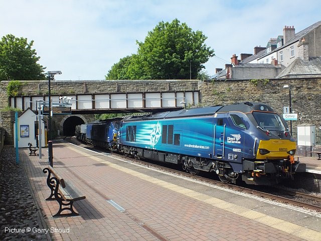
Neutral sections can enable OLE to be installed under structures with limited clearance. However, even if the OLE is not energised, significant clearances must be maintained to prevent the OLE or the pantograph from contacting the structure. Allowances must be made for installation tolerances (of both OLE and track), as well as movement of the wire due to pantograph interactions, ice and wind, and of the track due to settlement and tamping. This option is therefore typically only feasible for a small proportion of structures.
Fig. 18: Limited structure clearance © Garry StroudCompatibility
The scenario discussed above under ‘Operational Resilience’ illustrates how the basic requirements for the trains and the infrastructure could start to be worked out. For example:
- the battery capacity could be specified in terms of enabling the train to run for a certain distance at maximum tractive effort; and
- the infrastructure could be specified so as to enable such a train to be able to reach an electrified section or a station from any point.
Future-proofing
A train designed to routinely, safely and reliably traverse gaps of, for example, 3-4km today is likely to be able to be upgraded in 5-10 years’ time to be able to traverse longer gaps, simply by replacing the battery system with improved technology that is likely to become available in the intervening years.
This realisation should enable manufacturers and electrification planners to focus on specific systems (such as the TransPennine route) in the secure knowledge that, once they have installed a system that today’s trains can operate on, they can be sure that it will be more than suitable for tomorrow’s trains.
Fig. 19: Eurostar in London St Pancras station © Andy Pincock